A guide, written from an engineer's point of view, to springback in stainless steel sheet bending, the logic of minimum bend radius, bend allowance calculation, design rules, surface protection and grade differences.
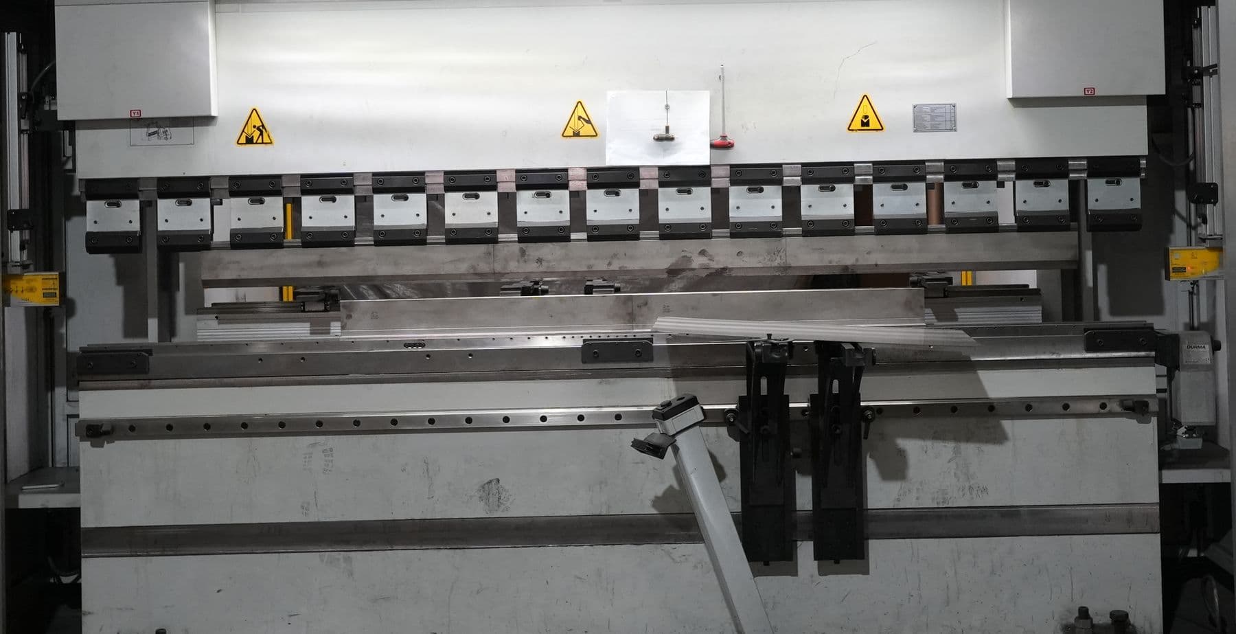
A stainless steel sheet and a mild steel sheet of the same thickness can be bent on the same press brake, but they do not behave the same. Stainless has a higher yield strength and work hardens as it is bent, so it both needs more force and springs back more after bending. The rest of the guide addresses the questions of why the angle does not hold, how tight it can be bent, how dimensions are calculated and how the surface is protected, based on standards and basic mechanics; the applicable limit is always determined on the machine and tooling and confirmed in the quote process.
During bending, the outer side of the sheet stretches and the inner side shortens. When the tool is withdrawn, the elastic portion of the material returns and the angle opens slightly. This is called springback. Springback increases as the material's yield strength rises and as the bend radius grows relative to thickness. Stainless steel therefore springs back more than carbon steel.
The compensation method is well known: the part is bent slightly more than the desired angle and, when it springs back, settles at the target angle. Since how much overbending is needed varies with material, thickness and tooling, the first part is bent, the angle is measured and the program is corrected. For this reason, first-part approval is the most important step in bending control. Bottoming and air bending methods affect the amount of springback differently; which one is used is chosen according to the part's tolerance.
What determines bendability is the ductility of the material. Austenitic 304 and 316, with their high elongation values, are suited to bending. In ferritic 430, although the yield strength is similar, the minimum elongation is noticeably lower; at the same radius and the same thickness it can crack more easily. The table below shows the minimum mechanical values in ASTM A240.
| Grade | Yield (MPa) | Tensile (MPa) | Elongation (%) | Family |
|---|---|---|---|---|
| 304 | 205 | 515 | 40 | Austenitic |
| 316 | 205 | 515 | 40 | Austenitic |
| 304L / 316L | 170 | 485 | 40 | Austenitic, low carbon |
| 430 | 205 | 450 | 22 | Ferritic |
The elongation on the outer surface of the sheet is determined by the ratio of the inside radius to the thickness. In an approximate model where the neutral axis stays at mid-thickness, outer surface elongation is calculated with the formula 1 / (2 x R/t + 1) (R is the inside radius, t is the thickness). As R/t gets smaller, elongation grows rapidly. The table below shows approximate values of this relationship; it is meant for building rough logic, and the real limit is found by trial according to the lot and processing condition.
| R / t | Outer surface elongation (%) | Comment |
|---|---|---|
| 0.5 | 50 | Very high elongation, not recommended without trial |
| 1 | 33 | High elongation, region near the ductility limit |
| 2 | 20 | Medium elongation |
| 4 | 11 | Low elongation |
| 8 | 6 | Very low elongation, springback more pronounced |
The length of the flat part is calculated from the dimensions after bending. The sheet length in the bend zone is found approximately with the formula BA = (π / 180) x angle x (R + K x t). Here angle is the bend angle in degrees, R is the inside radius, t is the thickness and K is the coefficient giving the position of the neutral axis. K is not constant; it varies with material, thickness, radius and method. That is why each shop uses the K value it has obtained with its own machine and tooling.
The practical conclusion is this: when producing the flat pattern of a drawing, talking with someone who knows on which machine and with which tooling the bending will be done is the safest way to get the flat part dimension right. Settle the flat pattern this way before laser cutting; cutting and bending are two links of one chain, and the details are in the laser cutting guide.
The V opening of the lower die is, as a general rule, chosen as roughly 6 to 12 times the material thickness. The length of the bend flange has a lower limit relative to the V opening; a flange that is too short cannot sit on the die and will not bend properly. Asking about parts with short flanges at the drawing stage is far better than redesigning later.
A hole very close to the bend line ovalizes in bending; sufficient distance must be left between the hole and the bend. If the bend line ends in a cutout or a protrusion, a small bend relief is cut to prevent tearing at the corner. Using the same inside radius on all bends in a part reduces the need to change tooling. Inward-facing bends that are too close together can prevent the tool from fitting into the part; the sequence of bends and the tool's access must be thought through from the start.
The most visible defect in stainless bending is the surface. Tool marks and rubbing lines on the part become permanent, especially on brushed (No.4) and mirror surfaces. For this reason protective film, polyurethane dies or tool protection are used. Because film can tear in bending, the film type and thickness on a brushed surface are chosen job by job.
The second risk is iron contamination. Iron particles left on tooling that has touched carbon steel can be embedded in the stainless surface and show up as rust stains at the first rain or in a wet environment. Using separate tooling for stainless work or protecting the tooling reduces this risk. On brushed surfaces, whether the bend is perpendicular or parallel to the grain direction affects both the appearance and the cracking behavior; the rolling and grain direction should be indicated on the drawing. For surface types, see the surface types article.
If no other tolerance is specified in the drawing and ISO 2768-1 is referenced, general tolerance class m limits the angular deviation according to the leg length. As the leg gets longer, the permitted angular deviation decreases. These values are a general reference; for a part requiring a tight tolerance, it must be written explicitly in the drawing and feasibility must be settled in the quote process.
| Length of shorter side (mm) | Limit deviation |
|---|---|
| Up to 10 | ± 1° |
| Over 10 up to 50 | ± 0°30' |
| Over 50 up to 120 | ± 0°20' |
| Over 120 up to 400 | ± 0°10' |
| Over 400 | ± 0°5' |
Bending at the Güven Paslanmaz service center is done with a CNC press brake; for the cutting work before bending, the CNC laser cutting line is in the same service. Thickness and bend length limits are settled in the quote process according to the part and material. You can send the drawing together with grade, thickness, surface and quantity information through the quote form.
Price varies by grade, size, quantity and market; reach us through the quote form. Details of the bending line are on the bending page.
Material values are based on ASTM A240 and EN 10088-2. For general tolerance, ISO 2768-1 is referenced, for surface definitions ASTM A480 and EN 10088-2, and for surface cleaning ASTM A380. The outer surface elongation formula is a simple mechanical assumption in which the neutral axis stays at mid-thickness; real bending varies from this. There is no single standard value for minimum bend radius; the limit is determined by trial according to the material lot, its hardness and the bend direction.
Its yield strength is higher than carbon steel and it work hardens in bending. As a result there is more elastic recovery after bending, and the part is compensated by overbending beyond the target angle.
There is no single value. It depends on grade, thickness, hardness condition and bend direction. The inside radius is chosen relative to thickness to limit outer surface elongation, and the limit is confirmed with a trial bend.
304 bends more easily. In ASTM A240 the minimum elongation is 40% for 304 and 22% for 430; ferritic 430 cracks more easily at a tight radius.
Protective film, polyurethane dies or tool protection are used. These measures are especially important on brushed and mirror surfaces. Using separate tooling for stainless reduces iron contamination.
Taking the bend axis perpendicular to the rolling direction (so that the stress is along the rolling direction) generally reduces the risk of cracking. If grain direction matters for appearance, state this in the drawing.
With the formula BA = (π / 180) x angle x (R + K x t). K determines the position of the neutral axis and varies with material, radius and method; the calculation is usually done with the shop's own K value.
At Güven Paslanmaz, CNC laser cutting and bending are in the same service. You can request a quote with the drawing and bending information.

